
What is computed laminography?
Computed laminography (CL) is a form of X-ray computed tomography for flat and large parts. Instead of rotating the part about an axis perpendicular to the beam, it scans the part at an oblique angle, so no X-ray has to travel along the plane of a circuit board or a composite panel.
CT and laminography compared
The difference is the tilt of the rotation axis: perpendicular to the beam in CT, tilted against it in laminography.
Computed tomography (CT)
Computed laminography (CL)
How computed laminography works
In conventional CT, a part rotates once about an axis perpendicular to the X-ray beam, and the detector records a projection at every angle. For a flat part, the rays that run along its plane pass through its whole width. Almost no photons get through, and those projections add noise and streaks instead of information. A wide part also keeps the source at a distance, which limits the magnification.
Laminography tilts the scan axis against the beam, or moves the source and detector on paths parallel to the part. Every ray then crosses the part at an angle and only passes through its thickness. The detector records hundreds to thousands of projections from these oblique directions, and a reconstruction algorithm computes the 3D volume from them. The tilt angle measures how far the rotation axis leans away from its position in conventional CT, where it stands perpendicular to the beam. At 0°, the scan is a conventional circular CT.
The price is that no ray passes along the plane of the part. A cone of directions is never measured, so the volume is sharp in the plane of the part and blurrier in the depth direction. The missing cone opens with the tilt angle: the larger the tilt, the blurrier the depth direction.
When laminography is the better choice
Flat parts with a large aspect ratio, such as printed circuit boards, panels and wafers.
Parts too large to rotate in the cabinet, or that the source would collide with at high magnification.
Regions of interest inside a large part, for example a single solder joint or a CPU socket on a full board.
Layered structures where the planes of the part matter most: solder joints, vias, bonds, glue lines and composite plies.
Laminography scan geometries
Systems reach the oblique view in different ways. Each one changes what the reconstruction has to handle.
Conventional circular CT
How it works: The part rotates 360° about an axis perpendicular to the beam. This gives the most complete data for compact parts.
Limits: For flat parts, rays along the plane barely get through, and the size of the part limits how close the source can come.
Tilted rotation axis
How it works: The part rotates on a turntable whose axis is tilted against the beam, typically by up to about 30°. Several lab CT systems offer this as a scan mode.
Limits: Larger tilt angles lose more information in the depth direction. The part still has to fit on the turntable and inside the cabinet.
Detector shifting and translation
How it works: The part stays in place or moves along a line while the source and detector shift parallel to it. This suits inline inspection of boards and panels.
Limits: The range of viewing angles is smaller than with a full rotation, so the depth resolution drops further.
Robotic laminography
How it works: Two robot arms move the source and the detector along free paths around a part that stays in place. There is no size limit from a cabinet, and the paths can follow the part.
Limits: Robot arms position less accurately than the rails of a lab CT, so the geometry has errors that blur conventional reconstructions.
Laminography results
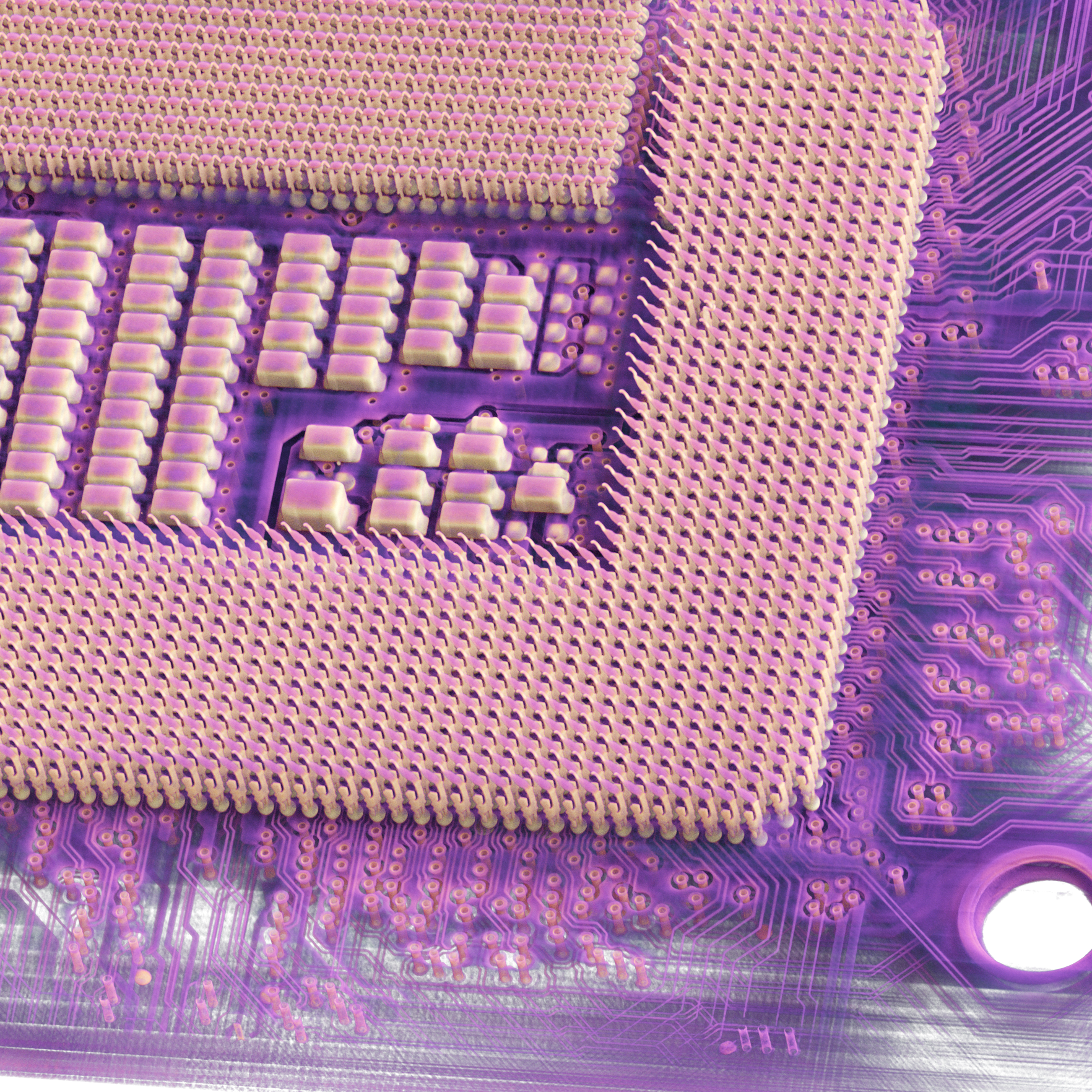
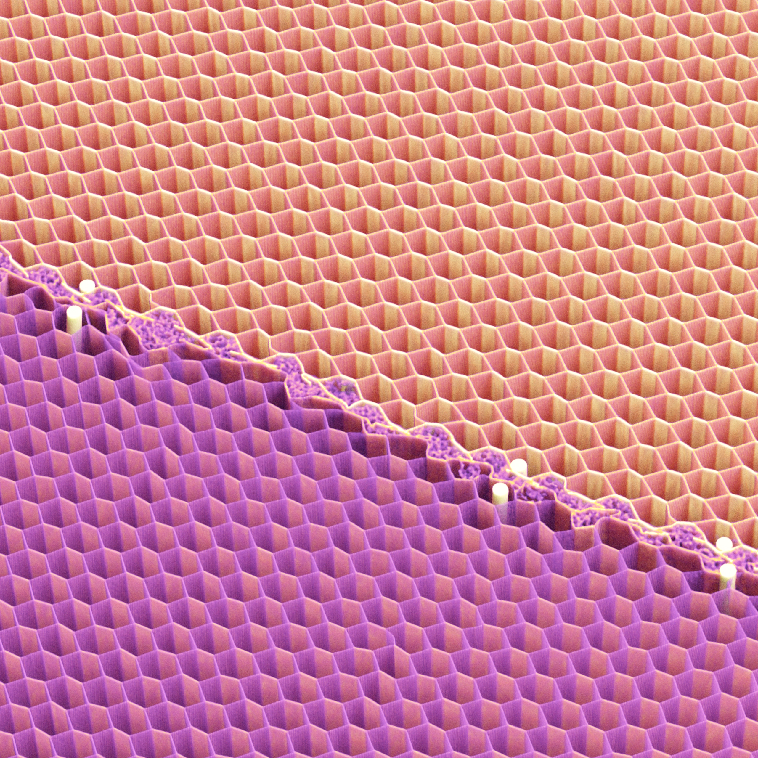
Details from laminography scans reconstructed with Voxray QRT.
How Voxray QRT reconstructs laminography
Filtered backprojection (FDK) was derived for circular scans. On laminography data, it adds artifacts on top of the blur that comes from the scan geometry. QRT reconstructs from the actual position of the source and the detector at every projection, so every laminography geometry and any other trajectory works with the same algorithm.
No reconstruction can measure directions that the scan never recorded. QRT gets the most out of the projections that were recorded: it corrects the geometry, keeps the solder and copper from spreading streaks, and does not add undersampling artifacts.
Every laminography geometry
Tilted rotation axis, detector shifting and robotic laminography, plus any custom trajectory.
Geometry correction for every projection
Positioning errors of robot arms and stages are corrected automatically during the reconstruction.
Fewer metal artifacts
Solder, copper and pins are reconstructed in the same physical model as the board around them.
Your scanner's raw data
QRT reads laminography data from Nikon, Waygate, Zeiss, Comet Yxlon, RX Solutions, Viscom and Techvalley scanners, and custom systems through the Voxray projection format.

Case study
Robot CT laminography of a motherboard
Omni NDE scanned an entire motherboard with their twin-robot CT system in a laminography trajectory: 17,689 projections at 30 µm. QRT corrected the positioning errors of the robot arms and reconstructed the full board, from the CPU socket to single solder joints.
Read the case study
Frequently asked questions about laminography
What is the difference between CT and laminography?
In CT, the part rotates about an axis perpendicular to the X-ray beam. In laminography, the axis is tilted against the beam, or the source and detector move parallel to the part, so the rays cross a flat part at an angle instead of along its plane.
What is computed laminography used for?
For flat or large parts that CT can't scan well: printed circuit board assemblies, semiconductor packages, wafers, composite panels in aerospace, and regions of interest inside large parts.
Why are laminography volumes blurrier in the depth direction?
Laminography never measures rays along the plane of the part. This missing cone of directions blurs structures in the depth direction, while the plane of the part stays sharp. Smaller tilt angles reduce the effect, but the rays then run closer to the plane of a flat part and pass through more material.
Is laminography faster than CT?
Often, for flat parts. Every ray crosses only the thickness of the part instead of its full width, so more photons get through and exposures can be shorter, and no projections are spent on rays along the plane. How much faster depends on the part and the system.
Which laminography data can Voxray QRT reconstruct?
QRT supports tilted rotation axes, detector shifting and robotic laminography. It reads laminography raw data from Nikon, Waygate, Zeiss, Comet Yxlon, RX Solutions, Viscom and Techvalley scanners, and any trajectory through the Voxray projection format.
Can I test QRT on my own laminography scans?
Yes. Request a free trial and reconstruct your own datasets on your workstation, or choose the reconstruction service and send us a dataset to reconstruct for you.
Related topics
Reconstruct your laminography scans with QRT
Try QRT on your own laminography data in a free trial, or talk to us about your parts and your scanner.