
Guide
The Voxray projection format for CT

Fabian Rückert
- last updated on Oct 26, 2026
Geometry format version
For your convenience we are aiming to support raw CT scanner data formats of all major scanner OEMs directly inside the Voxray software application.
If you have a custom-built CT scanner and want to use the Voxray software without us having to do the data format conversion or want to otherwise experiment, you can use the Voxray projection format described on this page.
We support two different ways of specifying the projection geometry:
circular: for circular CT trajectories (supports helix CT).
astra_cone_vec: for arbitrary trajectories (matches the geometry definition of the Astra Toolbox).
All data for one dataset lives in a directory, called the root_dir. The root_dir contains one subdirectory for each scan. scan0, scan1, etc.
We describe the contents of a scan directory in the following.
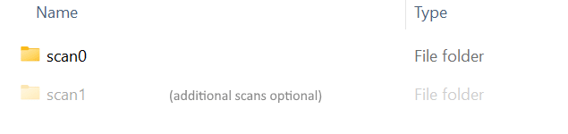
root_dir/ folder contents
All positions, directions and volumes are given in one right-handed world frame (units in mm):
z is the rotation axis of circular scans and points down.
The origin is the rotation center, src_2_origin_mm from the source when there are no shifts.
At angle 0 the source is on -x and the beam points along +x. Image right is +y, image down is +z.
Projections are seen from the source, looking along the beam: pixel (0, 0) is the top-left corner, columns go to the image right and rows go down.
Object shifts and rotation_axis_horizontal_shift_mm move the source, so the object moves by the negative value.
Slice 0 of an exported volume is its top (-z).
This frame only applies to circular scans. For astra_cone_vec, the frame is the one the cone vectors are given in, and the [Volume] position uses the same frame.
The circular format allows you to specify circular CT trajectories. This includes helix CT scans. It is enabled by setting type=circular in the dataset.ini file.
A complete scan, living in the root_dir/scan0 directory, should look like this:

root_dir/scan[n] folder contents
In the following, we describe the content of each file.
The dataset.ini contains all static data describing a dataset. The following describes a dataset in the circular format. For arbitrary trajectories use the astra_cone_vec format.
./dataset.ini
This file is optional.
The optional reco.ini file can be placed in root_dir and stores initial reconstruction parameters.
./reco.ini
The file preprocessing.ini contains preprocessing parameters for preprocessing the projections.
./preprocessing.ini
The file volume.ini contains the parameters for the reconstruction volume. If an optional roi-volume.ini is present, volume.ini defines the overview volume, which must contain everything visible in the projections.
./volume.ini
This file is optional.
The optional roi-volume.ini file defines a region-of-interest (ROI) volume for dual-volume reconstruction. When present, volume.ini specifies the overview volume and roi-volume.ini specifies the ROI volume: the region that is reconstructed at high resolution and written to the output file.
The file uses the same [Volume] section as volume.ini. The relevant fields are volume_translation_mm and volume_sidelength_x_y_z_mm. The voxel size and rotation is taken from volume.ini. The ROI volume must fit inside the overview volume.
./roi-volume.ini
The [list_file].txt (for example projections.txt, flatfields.txt, darkfields.txt, alignment-projections.txt or masks.txt) files contains the filename of each projection that is located in the directory given by the respective section [Projections], [Flatfields], [Darkfields] or [Masks] in the dataset.ini.
The order is important. Row N corresponds to the projection N. We support 16bit uint, 32bit float PNGs, TIFs, or Raw intensity projections. The projections must not be in log-space.
The masks.txt file can also contain empty lines, which means that the corresponding projection is not masked.
./[list_file].txt when storage_mode=ImageList
./[list_file].txt when storage_mode=Blob. Each line contains the byte offset of the projection in the blob file.
This file is optional.
The optional detector-shifts.txt file contains an optional detector shift (in pixels) for each projection stored as (x y) per line and projection. It is subtracted from the principal point of that projection.
./detector-shifts.txt
This file is optional.
The optional obj-shifts.txt file contains an optional object shift (in mm) for each projection stored as (x y z) per line and projection.
./obj-shifts.txt
This file is optional.
Instead of specifying the angles via angle_step_deg and start_angle_deg, it is also possible to specify the angle for each projection explicitly using an angles.txt file. This enables specifying non-uniformly distributed angles.
./angles.txt
This file is optional.
Specifies angles at which the respective alignment-projection has been captured. If 7 alignment projections have been captured with a step of 60 degrees this file should look like this:
./alignment-angles.txt
In this article