
What is robot CT?
Robot CT (robotic computed tomography) moves the X-ray source, the detector or the part with industrial robot arms instead of a turntable in a cabinet. The scan can follow the part along almost any path, so parts that are too large, too flat or too heavy for a CT cabinet can be scanned where they are.
How robot CT works
A conventional CT system rotates the part on a turntable between a fixed X-ray source and a fixed detector. Robot CT replaces these fixed axes with robot arms. In the most common setup, twin-robot CT, one arm holds the source and the other holds the detector, and both move around a part that stays in place. Other systems hold the part with a robot and keep the source and detector fixed.
Because the arms move freely, the scan path is no longer limited to a circle. Robot CT can scan a region of interest inside a large structure, follow the outline of a part, or move the source and detector parallel to a flat panel for robot laminography.
The flexibility has a price. Robot arms position less accurately than the axes of a lab CT: vibration, gravity and the bending of the arms move the source and the detector by fractions of a millimetre away from the positions the controller reports. At voxel sizes of a few micrometres, these errors blur the volume and add double edges. On top of that, filtered backprojection, the standard algorithm in most CT software, was derived for circular scans, and its standard implementations can't reconstruct free robot paths directly. Robot CT therefore usually needs a geometry calibration for every scan and reconstruction software built for arbitrary trajectories. Voxray QRT covers both: it reconstructs any path and corrects the geometry from the scan data itself.
When robot CT is the better choice
Parts too large or too heavy for a CT cabinet, such as aircraft panels, car body sections and large castings.
Flat parts such as composite panels and circuit boards, scanned with robot laminography.
Regions of interest inside an assembled structure, such as rivets, welds and adhesive joints, without taking it apart.
Inspection on site, where a mobile robot system comes to the part instead of the part going to the lab.
Scan paths planned around the part: they steer around fixtures and other obstacles, and take more views from the directions that show the feature you inspect, such as a weld seam.
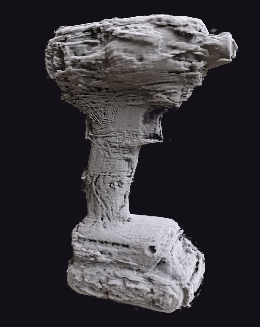
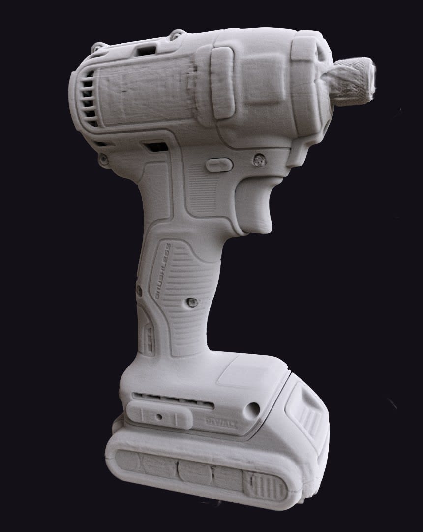
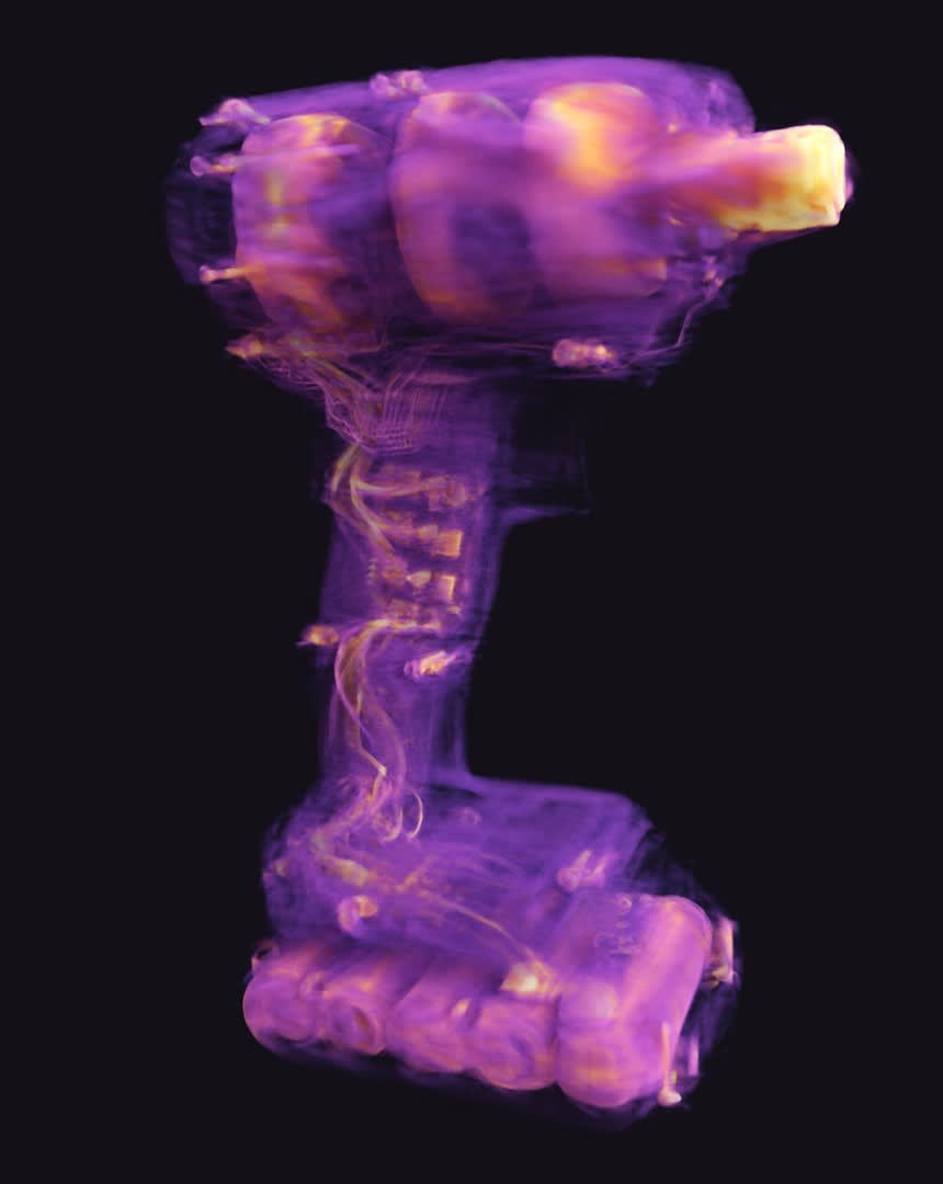
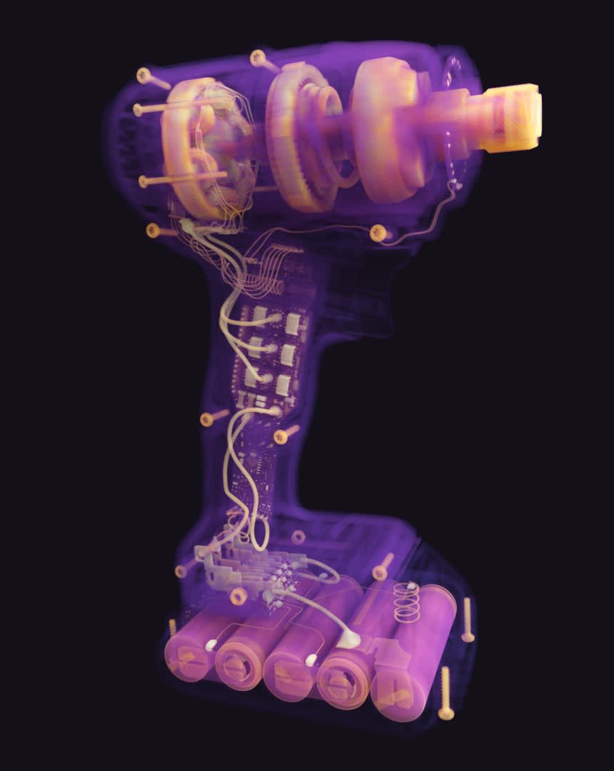
Robot geometry errors, with and without correction
A robot CT scan of a cordless drill, reconstructed from the uncorrected robot poses and with Voxray QRT's geometry correction.


Robot CT setups
Robot CT systems differ in what the robots move. The setup decides which scan paths are possible and which errors the reconstruction has to correct.
One robot moving the part
How it works: A robot arm holds the part between a fixed source and a fixed detector and turns it through the beam, often inside a radiation-shielded enclosure. The distance between source and detector stays constant.
Limits: The part has to be small and light enough for the robot to hold, and the positioning errors of the robot still affect every projection.
Twin-robot CT
How it works: One robot carries the X-ray source and a second robot carries the detector. Both move around a part that stays in place, so the geometry can change from one projection to the next.
Limits: Both arms add their own positioning errors. The robots have to move in sync and stay clear of the part and of each other.
Robot laminography
How it works: The two robots move the source and the detector in parallel on either side of a flat part, so every ray crosses it at an angle. This suits composite panels and circuit boards that a circular scan can't penetrate.
Limits: As in all laminography, rays along the plane of the part are never measured, so the volume is less sharp in the depth direction than in the plane.
Multi-robot systems
How it works: Large installations use more than two robots to reach around very large parts. Fraunhofer's RoboCT system at BMW, in operation since 2018, uses four robots to inspect joints in prototype car bodies.
Limits: These systems are large and expensive, and every robot adds geometry errors that the reconstruction has to handle.
Planning a robot CT scan
With free scan paths, the path itself decides how good the volume can be.
Complete data
Aim for: Rays from enough directions through every structure you want to see. As a rule, every plane through the region of interest should cut the path of the source at least once (Tuy's condition).
Watch out for: Paths that leave out a range of directions blur the edges that run along the missing rays. Flat parts always lose the directions along their plane.
Reach and collisions
Aim for: A path that brings the source close to the part for high magnification while both arms stay within their reach.
Watch out for: Fixtures, the part itself and the other robot limit the poses. Simulate the path before the first scan.
Large parts and truncated projections
Aim for: Scanning only the region you need, at the magnification you need, even if the part is wider than the detector.
Watch out for: When the part extends beyond the detector, the projections are truncated. Filtered backprojection then produces bright rims and cupping at the edge of the field of view.
Number of projections
Aim for: Enough projections for the voxel size you need. Robot CT systems often record thousands; the motherboard scan below has 17,689.
Watch out for: Every pose takes time to reach and settle. Fewer projections shorten the scan, but cause undersampling streaks with filtered backprojection.
How Voxray QRT reconstructs robot CT
QRT reconstructs from the position of the source and the detector at every single projection. Any path the robots can drive works with the same algorithm, whether it is a circle, a helix, a laminography path or a path planned around the part.
The poses that the robot controller reports are enough as a starting point. QRT corrects the geometry of every projection from the measured data during the reconstruction itself, so robot CT needs neither a calibration phantom nor a separate calibration scan.
No calibration scan
QRT corrects the poses of the source and the detector for every projection from the scan data. No calibration phantom is needed.
Every robot, every trajectory
The Robot CT module supports single-robot, twin-robot and multi-robot systems and any scan path.
Robot laminography
The same reconstruction handles laminography paths for flat parts such as composite panels and circuit boards, as in the motherboard scan below.
Open data format
Robot CT systems pass their projections and the pose of every projection to QRT in the Voxray projection format.

Case study
Robot CT laminography of a motherboard
Omni NDE scanned an entire motherboard with their twin-robot CT system in a laminography trajectory: 17,689 projections at 30 µm. QRT corrected the positioning errors of the robot arms and reconstructed the full board, from the CPU socket to single solder joints.
Read the case study
Frequently asked questions about robot CT
What is robot CT?
Robot CT is X-ray computed tomography in which industrial robot arms move the X-ray source, the detector or the part. It replaces the fixed turntable of a CT cabinet with free scan paths, so large, flat or fixed parts can be scanned.
What is the difference between single-robot and twin-robot CT?
In single-robot CT, one robot moves the part between a fixed source and detector. In twin-robot CT, one robot carries the source and another carries the detector, and both move around a part that stays in place.
Why does robot CT need geometry correction?
Robot arms position less accurately than the axes of a lab CT. Vibration, gravity and the bending of the arms move the source and the detector by fractions of a millimetre, which blurs the volume at micrometre voxel sizes unless the geometry of every projection is corrected. The standard implementations of filtered backprojection, the algorithm in most CT software, also can't reconstruct free robot paths directly. Voxray QRT reconstructs any path and corrects the geometry from the scan data itself.
Does Voxray QRT need a calibration phantom for robot CT?
No. QRT starts from the poses that the robots report and corrects the geometry of every projection from the scan data during the reconstruction.
Which robot CT systems does QRT support?
The Robot CT module supports every robot type and every trajectory: single-robot, twin-robot and multi-robot systems. Systems pass their data to QRT in the Voxray projection format, with the source and detector pose of every projection. Omni NDE's twin-robot systems are reconstructed with QRT.
Can robot CT scan parts larger than the detector?
Yes. The robots can scan a region of interest inside a large part, for example a single joint in a car body, at the magnification that region needs.
Can I test QRT on my own robot CT scans?
Yes. Request a free trial and reconstruct your own datasets on your workstation, or choose the reconstruction service and send us a dataset to reconstruct for you.
Related topics
Reconstruct your robot CT scans with QRT
Try QRT on your own robot CT data in a free trial, or talk to us about your robot system and your parts.